DSC06245.jpg

spin

DSC06245.jpg

spin

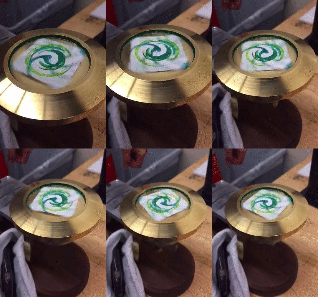
A spin-art generating Stirling Engine. The engine features a single piston and a displacer that shuttles the air back and forth between the heat sink and the heat source applied at the end of the stainless steel end cap. I custom designed 9 of 17 components that I precision machined.

On testing day, my engine ran at 1589rpm, ranking third fastest among 35.

Mechanical Engineering | Manufacturing

06 01 2017 - 08 29 2017

Individual

 
enginepaintings.jpg
 

design

3web.JPG
5web.JPG


fabrication

I created full engineering drawings of the engine to adhere to the appropriate tolerances, and machined all of the parts using both manual and Numerically Controlled milling machines and lathes. The components are all within +/- 0.004” tolerance to allow for a functional assembly.


tolerance stack up

Performed a tolerance stack up to determine the maximum displacer diameter that will ensure assembly and prevents interference between the displacer and inner diameter of the heat sink and air chamber.

RESULTS

Max Diameter Displacer Chamber: 0.897825”

ASSUMPTIONS

The following Tolerance Stack up was performed with the following general assumptions:

  1.  Unless otherwise specified (given parts), concentricity tolerance of lathe is +/- 0.002” through online research

  2.  Assembly holes (x2) on heat sink, mounting block, and air chamber are vertical and equidistant from the center of each respective part (0.672”)

  3.  Perpendicularity is perfect while straightness tolerance is considered

  4.  Straightness tolerance on mill and ProtoTRAK are +/- 0.002” (mostly due to dirty parallels, presence of burs)

  5.  Straightness on lathe +/- 0.002”

  6.  Worst case found when displacer chamber is furthest into heat sink/air chamber assembly

METHOD

I first narrowed down the entire assembly to pieces that I felt altered the placement and size of the displacer chamber the most (bushing, DBT, mounting block, displacer, heat sink, air chamber). I then established that the worst case of this sub assembly would be if the bushing, DBT, rod, and mounting block were shifted the furthest downwards (- y direction, side 1) while the heat sink, cold cap, and air chamber were shifted upwards (+y, side 2) as far as tolerance would allow. This separated my analysis into two portions.

I established a worst case for each individual component (see following spreadsheet) given the tolerances indicated on the engineering drawings or assumed through research. I then calculated the total deviation upwards/downwards of each half without considering straightness. Note when calculating the deviation due to diameter tolerances, I simply shifted the feature up/down by half the tolerance since the total distance moved would only be the difference between the deviated diameter and perfect diameter. I calculated deviations due to straightness separately to better visualize the situation and added that value into the previous deviations to get the shift factor. The resulting number for side 1 of the assembly would give me the y-distance between the center of the displacer chamber and perfect center of the assembly. The resulting number for side 2 would give me the y-distance between the center of the heat sink and the perfect center of the assembly.

I added that value to the original distance between the center of the assembly and the inner edge of the heat sink. Finally, I subtracted the deviation of side 1 from side 2 to give the maximum radius of the displacer chamber physically possible under worst-case assumptions and tolerances. Considering that the displacer chamber given to us is 1” in diameter while the max I calculated here is 0.8725”, either the teaching staff has confidence that we students will not achieve 0.9825” worst case in machining, or some of my assumptions were overestimated. 

 
TSU.jpg
GDT.jpg

gd&t

Produced a detailed description of the equipment, procedure, and data processing to verify perpendicularity of the piston and piston connecting rod assembly hole

GIVEN
The tolerance noted in the engineering drawing of the piston specifies that the outer diameter of the 0.1247 reamed hole can be offset by a circle of up to 0.003" in diameter at MMC (maximum material condition)

EQUIPMENT & REQUIREMENTS
-Rod/shaft to be inserted into the piston (therefore must be close fit diameter with the 0.1247” reamed hole)
-Shaft must be longer than piston width
-Qualified surface/plate
-Dial indicator/calipers
-Leveler

METHOD
Find the reference datum plane, the slit of the piston called out as A in the engineering drawing of the piston below. To do this, pin the qualified plate by using a leveler and evenly facing the sides of the plate precisely to the opposite end of the piston. Insert the shaft through the reamed hole until it is in contact with the plate. Make a line along the edge of the shaft as a reference datum. Measure the distance from this line, along the length of the piston at 3 points: the top of the rod, the top of the hole, and the bottom of the hole. One is now able to use trigonometry to calculate the distance the edge of the cylindrical rod has traveled away from its datum (the red line and yellow line in the drawing below). The difference between the red and yellow line lengths is equal to its offset from perfect perpendicularity.


testing

 
ezgif.com-gif-maker.gif
 
4web.JPG